
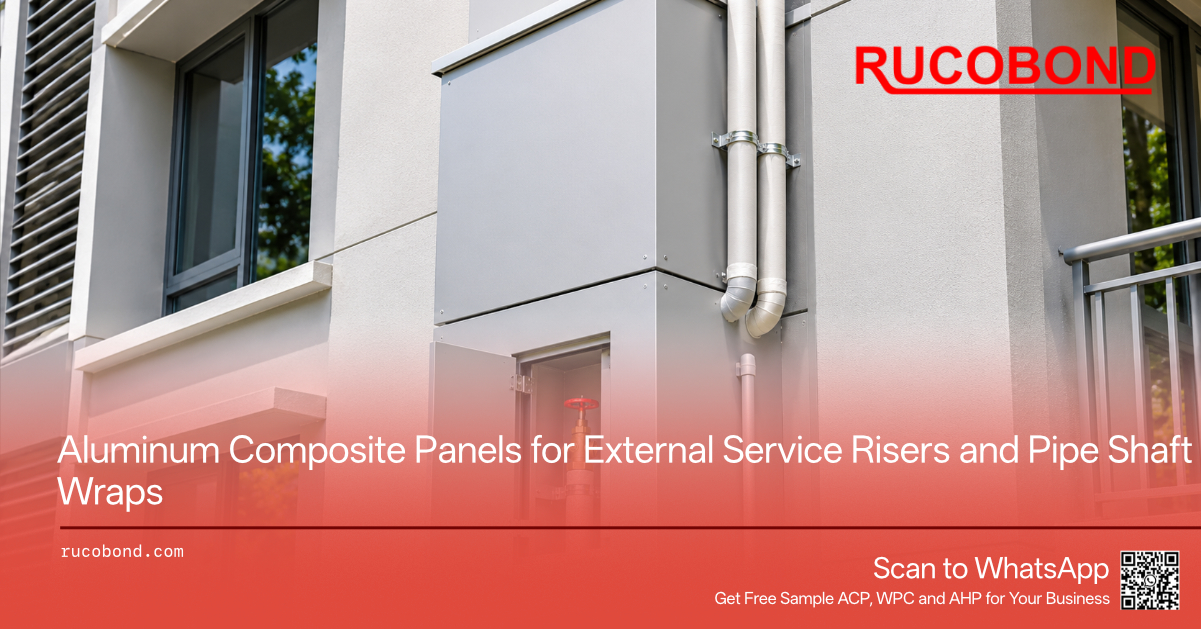
On a mid-rise apartment elevation, the repeating vertical box beside the windows is often not a column. It is a service riser: a cover around soil and waste stacks, water pipes, and condensate drain lines serving indoor air-conditioning units, routed story after story through that external box. The structure is typically a concrete frame with masonry infill, or a concrete wall, and those services have to travel the height of the building. If they are left exposed, the pipes, clips, and insulation become part of the street view. If they are boxed, the box becomes a third kind of metal work on the same wall, sitting alongside punched window surrounds and balcony edges, but doing a different job.
The riser is a volume around live services, not a decorative pilaster drawn only in elevation. Valves, cleanouts, and meters have to remain reachable after the cladding is in place. Pipes leave the box at floor branches, at connections serving indoor units, and sometimes at a roof tank or a ground-floor outlet, so the wrap has openings and closures, not only a flat face. Water from condensate drains and occasional leaks can run inside that volume, and rain sits on the weather cap at the head of the wrap, not on every lift. Those are the conditions that stain a vertical face, and they are not the same as dust on a window sill or wash water leaving a balcony floor.
On mid-rise apartment walls typical of work in Southeast Asia and in Pakistan, those conditions already differ from street to street. A humid, rainy elevation, as in Singapore or Bangkok, and a shaded side of the box keep the metal wet longer, and water from a condensate drain or from sweating pipes can leave long streaks if a joint or a collar is poorly closed. A coastal street, as in Karachi, loads salt and dust onto the windward face. A hot inland summer, as in Lahore, loads airborne dust onto the cap ledge, then wets that dust in heavy rain. Those conditions change how the riser is soiled and how carefully outlets and the cap must be formed. They do not produce one standard riser detail, and they do not turn every vertical box into the same wall type.
If the box is taken only as a narrow band on the elevation drawing, the shop is left without the projection from the wall, the access openings, and the pipe outlets. The cover then comes out tight on the pipes, or the face is cut later on site, or the metal is asked to hold a pipe that should have been clipped to the structure. The riser has to be drawn as a wrap around a service volume, with a face, returns, a way in for maintenance, and a clear joint to the adjacent wall.
The field wall is the cladding on the main elevation. It may stop at a joint beside the riser, or it may meet a closer flashing at the wall, but it remains a wall face. The riser wrap is a three-sided cover in most apartment work: a finished outer face and two returns that run back to the wall, leaving the fourth side open against the structure. That U-shaped cover is not a structural column cover. A column is a load-bearing member being dressed. A riser is a service volume being enclosed, and it has to open.
The face is the visible front of the box, the plane seen in elevation. The two returns set the projection from the adjacent wall. Their depth is the distance from the wall cladding plane, or from the wall finish where the wrap meets the wall, out to the finished face of the riser. A short inward hem or fixing flange at the wall is not part of that visible projection; it belongs on the developed blank of the piece that carries it. Soil stacks, water risers, and other vertical pipes often run continuously through several stories. The ACP wrap can be installed in lifts, but that does not mean each lift needs a fully closed cap. A terminal weather cap belongs at the head of the whole external wrap, where the box ends, so that rain does not fall straight into the cavity. Between lifts, the usual detail is an intermediate horizontal joint: a break for installation, for movement, and for a weather closure at the joint, not a lid that stops the pipes. Firestopping or compartmentation at a floor slab, where the project requires it, is a separate construction. A decorative horizontal joint in the cladding does not provide that separation by itself. A skirt or a downturned drip at the foot of the riser, or at the base of a lift where water should be thrown off, is also a horizontal piece. The terminal weather cap and a three-sided base closure do not automatically belong on the same sheet as the vertical U.
The access leaf is the panel that opens. It is a separate piece set into an opening in the face, or it is a removable front panel, with the returns left fixed. A scored or dummy joint that only looks like a door is not an access opening. If a valve, a cleanout, or a meter sits behind the face, the opening has to land on that fitting, with enough margin in the face for the leaf, the rebate or flush bead, and the fixings, and with enough clear opening to use a tool on the fitting. A recessed chase, where the pipes sit in a notch in the wall and the face is nearly flush with the adjacent cladding, is a different geometry from a projecting box: the "returns" are then the cheeks of the recess, and the finished face width is set by the recess, not by a box standing off the wall.
This wrap should also be kept distinct from two neighbors on the same building. A balcony fascia covers a horizontal slab edge and often a soffit under a usable floor. A rooftop plant screen stands around equipment on a roof. The riser is a vertical service box on the wall, story after story, and its openings, branch outlets, and the distinction between a weather cap at the head and a joint at each floor line are what set the metal apart from those other pieces.
An aluminum composite panel is a coated sheet that a fabricator can cut, route, and fold into a U-shaped cover, a face panel, or a return. On a riser, that is useful because the box should often continue the same coating as the adjacent wall, and because a rectangular projection can be formed from a flat sheet with a small number of folds. The panel can close the visible sides of the volume, take a planned joint at each floor line, and accept a separate access leaf. Rucobond supplies the material as panel sheet. Routing, folding, assembly of leaves and flashings, and installation remain with the fabricator and the installer.
The same sheet is not, by itself, a fire-rated shaft enclosure. A service shaft on an apartment building may have fire-separation or compartmentation requirements in the project documents and in the codes that apply at the project location. Those requirements attach to the complete construction: the lining, the substrate or framing, the joints, the cavity, and the closures where the shaft meets a floor slab, not to a product name or a coating alone. The core, the fire-performance requirements written for the project, and that complete construction must comply with the codes at the project location. Not every aluminum composite panel is suitable for every shaft condition. A wrap chosen only because it matches the wall color is not a substitute for a shaft construction that the project actually requires.
The panel is also not the pipe support, and it is not the waterproofing of the chase. Pipes, insulation, and valves should be clipped and closed to the structure or to a frame designed for them, so that the cladding can be removed or opened without the services coming loose. Dent resistance of a metal face is not a reason to stand on the wrap, hang a new pipe from it, or treat it as a hoist point. Wind resistance of the cover is a property of the wrap plus its clips or rails and the substrate, not a number that can be read from the sheet alone. Used within those limits, the panel does the work it is good at: a formed, coated enclosure around a service volume that still has to be maintained.
ACP is often the right metal for the long vertical face and for the returns when those faces should match the adjacent wall in color, gloss, and panel thickness. A one-piece U, or a three-piece wrap with a separate face, can be cut from the same batch as the wall cassettes, which keeps the riser from reading as a different product on the elevation. Where the box is simply a rectangular projection and the access openings are modest, that is usually enough of a reason to keep the main wrap in composite panel.
Access leaves often run better in solid aluminum. A leaf is opened and closed, sometimes with tools and a ladder on a narrow balcony or from a swing stage. It may take hinges, a lock, or a row of screws on a hanging strip. A solid sheet can take a tighter edge and a smaller door than a routed composite panel, and it will usually mark less after repeated opening. That is a surface and fabrication difference, not a claim that solid aluminum is a stronger structure. If the leaf is large and is meant to disappear into the same wall finish, ACP can still be used for the door, provided the leaf is a separate piece and the margins around the opening are wide enough for a clean rebate.
Coated aluminum coil is often the clearer choice for the small flashings that finish the box: a top cap, a base skirt or drip, and the collars around pipes that leave the wrap. Those pieces are narrow, they may need a tight bend, and they are asked to throw water or close a hole rather than to present a wide painted face. Forming them from coil, or from a solid-aluminum flashing, keeps the main ACP wrap as a simple U and avoids asking one routed sheet to grow a cap, a drip, and a door at the same time. A mixed riser is therefore common: composite panel for the visible wrap, solid aluminum for the working leaf, and coil-formed metal at the cap, the base, and the outlets. The joint between those metals is seen in sun against shade, so color, gloss, and the direction of the finish have to be coordinated, but each piece is then asked to do work it can actually be formed to do.
The dimensions only make sense after the baselines are named. Finished face width is the visible width of the outer face, measured between the two vertical fold lines at the outer corners when those folds sit at the corners. Return depth is the finished projection from the adjacent wall plane out to that face. Developed blank width is the flat width of the sheet before folding, for the piece being described. Finished panel height is the visible height of one lift, between horizontal joints. Developed blank length is that height plus any flanges, hems, or upstands that belong to the same piece in the height direction. None of these should be treated as a catalog standard or as a promise of supply; they are a way to keep an example consistent.
Take a projecting box, not a recessed chase, as an illustration. The finished face width is 500 mm. Each return is 200 mm deep, measured from the adjacent wall cladding plane to the finished outer face. Each return has a 20 mm inward fixing flange at the wall. Those flanges do not reduce the 200 mm projection, and they do not reduce the 500 mm face; they are added on the developed blank. A one-piece U-wrap then has a developed blank width of 20 + 200 + 500 + 200 + 20 = 940 mm. The fold path is a continuous U in plan: flange, return, face, return, flange. That chain can be routed and folded from a single sheet.
An access leaf does not come out of that same blank as a hinged door. If a 300 mm wide opening is cut in the 500 mm face, centered on the face, each side margin is (500 - 300) / 2 = 100 mm. Those margins have to accept the edge of the opening and the leaf rebate or bead; 100 mm is already a tight margin, and it is a reason to check the opening width against the fittings behind it rather than to force a wide door into a narrow face. The leaf itself is a second piece. A four-sided box, a top cap that closes three sides, or a base flashing that turns down on the face and both returns, would require folds that branch from one corner in more than one direction. A routed composite sheet can follow a continuous chain, but it cannot branch into a vertical U and a horizontal cap or a three-sided skirt at once. The usual fabricable build is a vertical U, or a face plus two returns as separate pieces, with the cap and the base flashing cut from coil or from a separate sheet.
Height is set on a different axis. On an illustrative 3,000 mm floor-to-floor, a 10 mm intermediate horizontal joint at the head of the lift gives a finished panel height of 2,990 mm. That joint is a break in the cladding; the soil stack and the water riser can continue through it. If 20 mm fixing flanges are folded at the top and the bottom of that lift, they do not reduce the 2,990 mm face; they add to the developed length: 20 + 2,990 + 20 = 3,030 mm. That single-lift blank, at 3,030 mm, still has to be checked against the available sheet dimensions and the fabricator's routing, folding, and handling capacity; a length below any one figure is not, by itself, a confirmation that the sheet can be supplied or formed. A two-story one-piece cover, taking both lifts as a single face with no joint at the floor line, would have a finished height of 2,990 + 10 + 2,990 = 5,990 mm and a developed length of 20 + 5,990 + 20 = 6,030 mm. Every developed blank should be checked against the available sheet dimensions and the fabricator's routing, folding, and handling capacity, particularly for multi-story panels. A two-story length raises production, transport, handling, folding, and installation questions that a single lift does not, and if the sheet or the shop cannot take it, the wrap should be made as separate lifts with a joint at the floor line, not forced as one over-long piece. The same check applies if a face-only upstand behind a terminal weather cap lengthens one blank; the returns need not grow the same upstand, and a notched blank or a separate flashing is often cleaner than assuming one rectangle can serve every side.
Pipes leave the box. A condensate drain may discharge at a floor or at the base of the riser, a water branch may enter a kitchen, and a waste stack may take a fitting at a floor. Refrigerant lines may also leave the wrap to reach an outdoor unit; that outlet is not the condensate drain. Each outlet is a hole in the wrap or, at the head of the riser, in the weather cap, and a raw cut in a composite panel is not a weathering detail. A fixed sleeve and a collar or a small flashing, usually formed from coil or from solid aluminum, should close the hole around the pipe so that rain and dirty water do not run into the cut edge or behind the face. The position of that outlet has to be known before the face is cut; a hole added later is how a stained streak starts under a service leaf.
Water on the finished face often starts as a condensate drain that weeps at a collar, or as a cold pipe that sweats where its insulation is broken. A loose joint will send a thin, regular line down the panel. That streak is not the same as dust sitting on a weather cap, and it is not the same as rain sheeting off a balcony fascia. It comes from the services inside the volume, or from water that has already left a drain or a fitting. Closing the collar can keep that water from running out through the cut, but it cannot make a leaking pipe or a broken jacket dry. The pipes, their insulation, and their drains have to be completed as a service installation.
Rain on the terminal weather cap is a different path. That cap sits at the head of the wrap, not at every floor-line joint, and it should throw water off so that it does not pond on a flat lid or run into the cavity. An intermediate horizontal joint between lifts is a weather closure at a break in the cladding; it is not a second cap, and it must not interrupt the pipes that continue past the floor. A drip at the edge of the cap, or a base skirt at the foot of the riser, only throws on water that has already reached that edge. It is not a gutter, and it is not a stand-in for a leaking pipe or for an open top. Unlike a balcony floor, the weather cap is not a usable paved surface with a planned floor drain; it is a closure at the head of a vertical box. Water that leaves it should not be directed onto a window, a neighbor's balcony, or a public walk as an afterthought.
Water also gathers inside the box. In a humid apartment block, broken insulation on a cold pipe can let moisture condense and run to the base, even when the outer ACP joints are tight. Leaking fittings add to that flow, and rain can enter at a poorly closed joint or raw outlet. The bottom of the riser should not be left as a sump. A planned path should drain or divert that water so it does not stand against the pipes and the panels. Some boxes also need a way to ventilate or dry the cavity, but an open vent should not be assumed for every shaft. Drain and ventilation details have to sit with the pipe insulation and with any firestopping required at the floors. The ACP wrap is the outer cover. It does not replace pipe insulation, leak repair, or an internal drain.
The wrap has to be fixed to a substrate that can carry it: furring or rails on the wall, or a light frame built around the pipe bank and anchored to the structure. The pipes themselves are not that substrate. If the panel is screwed to a waste stack or hung from a water riser, opening a leaf or replacing a dented face becomes a service problem, and the pipes pick up loads they were not set out to take. Clips, rails, and the spacing of fixings belong to the fabricator and the installer, working to the project specification; they are not a property printed on a flat sheet.
A column cover and a wall cassette are poor models for this fixing, even when the same coating is used. A column cover dresses a structural member and is often a four-sided or nearly four-sided wrap with no need for a maintenance door at every valve. A wall cassette is judged mainly as a flat elevation module. The riser is a projecting volume with a cavity full of services, and it needs a joint pattern that allows a lift to move slightly with temperature over the height of the wall. Horizontal joints at floor lines are the natural breaks. They also keep each lift within a length the shop can handle. A continuous face that runs two or three stories may look cleaner on a rendering, but it asks the sheet, the folds, and the handling gear to take a length that should first be checked against the available sheet dimensions and the fabricator's capacity, and it makes a local repair or a later pipe change harder. Segmented lifts, with the pipes running through the floor-line joints, let a damaged face be taken off one story without opening the whole height of the box or moving the stacks.
The access leaf needs a fixing of its own: screws in a consistent pattern, a hanging strip, or hinges and a stay, so that the leaf can be opened without loosening the returns. The returns can be fixed more permanently to the wall flanges. That split, and a wrap fixed to the wall or to a frame rather than to the pipes, is what allows one leaf or one dented face to be replaced without disturbing the pipe bank or the lifts above and below.
A riser that sits on a masonry apartment wall is usually meant to disappear into that wall, or at least to read as the same coating. Color, gloss, and the direction of a metallic or mica finish should be taken from the same batch discussion as the adjacent wall panels, including the side returns, which are seen in a different light from the face. A face in morning sun and a return in shade will already look slightly different; a second batch or a different gloss makes that difference permanent. The weather cap and the coil flashings, if they are a different metal, should be matched as closely as the finish system allows, because they sit as narrow highlights along the box.
Soiling on a riser is mostly vertical. Condensate or dirty water that leaves a collar or a face joint draws a line down the panel and is still visible from the street after the surface has dried. On a humid street, the shaded return stays wet longer and holds that mark. On a coastal street, salt and dust sit on the windward face and in the small ledge of the weather cap or of a joint flashing. On a hot inland street, airborne dust settles on that same ledge and then forms a crust when rain wets it. Those are scene differences, not three recipes for one wall. A weather cap with a real slope and a drip, and collars that actually close, do more for the look of the box than a darker color chosen only to hide streaks.
Cleaning is part of the same problem. A face that can be reached from a balcony or from a short stage can be washed; a face that stands in a tight slot between two wings of the building may hardly be reached at all. Finish choice should follow that fact rather than assume every riser will be washed on the same cycle as the main wall. Directional coatings should be laid out so that the length of the lift runs in a consistent direction, including any replacement leaf supplied later. The aim is a vertical box that still belongs to the wall after a few wet seasons, not a darker pilaster of dirt running the full height of the elevation.
The reason for a leaf is a fitting that someone will have to reach: a valve, a cleanout, a meter, a trap, or a junction that the building management will service. The opening in the face has to land on that fitting, not beside it, and those fittings should be located on a drawing before the face is cut. The leaf has to be large enough for a hand and a tool, and for the fitting to be taken out and replaced, not only for the valve to be visible. Depth inside the box matters as much as the size of the door: a wrench or a short section of pipe has to come out through the leaf without fighting the returns. A pattern of regular dummy joints that does not land on the fittings is decoration. A face with no opening, and a note that the panel can be cut later, usually means the later cut will land badly and will not be closed with a proper leaf.
Pipe supports, insulation, and any firestopping or cavity closure required at a floor slab belong to the service installation and to the shaft construction, not to the cladding. The wrap can be jointed or notched around a support that is already fixed to the structure. It should not be used as the clamp. A horizontal joint in the ACP at a floor line is a break in the cladding; it does not, by itself, provide that floor-level firestopping or compartmentation. New pipes added after occupation should be clipped to the structure in the same way, and a new outlet should be formed with a sleeve and a collar, not pushed through a raw slot in the composite face. Electrical and gas services, where they share a riser or sit in a neighboring shaft, have their own clearance and access rules in the project documents; the metal cover does not relax those rules.
Because the stacks and water risers continue through several stories, a dented face or a worn leaf should be removable as a cladding piece, lift by lift, without loosening the pipes or opening the lifts above and below. That is only possible if the wrap is fixed to the wall or to a frame, and if the leaf lines up with the fitting it serves. The ACP cover can then be maintained as cladding around services that stay in place.
A useful enquiry starts with a plan and a typical section through the box, not with the elevation pilaster alone. The section should show the adjacent wall plane, the finished projection, the finished face width, the pipes and their insulation, and the clearance inside the cover. It should say whether the wrap is a projecting U or a nearly flush face on a recessed chase. A schedule of lifts should give the floor-to-floor height, the intermediate horizontal joint at each floor line, and the finished panel height. Every developed blank should be checked against the available sheet dimensions and the fabricator's routing, folding, and handling capacity, particularly for multi-story panels.
The same package should say how the wrap is built. A one-piece U with a developed width set out from the flanges, the returns, and the face is a fabricable build for a simple rectangular box. A three-piece wrap, with a separate face, is often clearer once a large leaf is required. The access openings should be dimensioned and tied to the fittings behind them, and the leaf should be specified as a separate piece, in ACP or in solid aluminum. The terminal weather cap, where the wrap ends at the head of the riser, the base flashing, and the collars at pipe outlets should be shown as separate flashings where a branched fold would otherwise be assumed. A weather cap should not be assumed at every floor-line joint. Outlet positions, including condensate drain discharges, water or waste branches, and any refrigerant lines leaving to an outdoor unit, belong on the drawing before the face is cut. If the project has a drain or diversion path at the foot of the box, that should be shown as well.
Material notes can stay short and tied to the project: thickness, skin gauge, and core as specified; coating and finish direction, including a request to batch the riser with the adjacent wall; a brief note on whether the site is coastal or inland, because that affects soiling and the metal at the cap and the outlets, not because it produces a standard box. Fire-performance requirements for the shaft or for the wrap, including the core and the complete construction, should be copied from the project documents and from the codes that apply at the project location. The enquiry should also state that the material is required as panel sheet for the fabricator to form. With those details, Rucobond can supply sheet that follows the actual box, the leaves, and the wall finish, rather than a vertical stripe taken from the elevation alone.
Q: Can one ACP sheet wrap a service riser and also serve as the hinged access door? A: The vertical U can often be one piece: two returns and a face, with wall flanges, folded in a continuous chain. The access leaf should not be assumed to fold from that same blank as a hinged door. A door that opens is a separate piece, set into a planned opening in the face, or it is a removable face with the returns left fixed. A terminal weather cap that closes three sides, and a base flashing that turns down on three sides, are also separate pieces in a fabricable build, because those folds branch from the vertical wrap rather than continue it. That cap belongs at the head of the wrap, not at every floor-line joint.
Q: Is an ACP riser wrap a fire-rated shaft wall? A: No. A coated wrap around a pipe bank is cladding, not, by itself, a fire-rated shaft enclosure. If the project or the local codes require fire separation or a specific shaft construction, those requirements apply to the core, to the fire-performance requirements written for the project, and to the complete construction, including closures at floor slabs. A horizontal joint in the cladding at a floor line is not, by itself, that floor-level firestopping. Not every aluminum composite panel is suitable for every shaft condition. The requirements should be copied from the project documents and from the codes that apply at the project location, not inferred from the wall color or from a product name.
Q: Does a top cap or a base drip reduce the finished face width or the finished panel height? A: Not automatically. Finished face width is the visible front between the outer fold lines. Return depth is the projection to that face. A terminal weather cap or a downturned drip does not come out of those finished dimensions unless it actually occupies the face. It belongs on the developed blank of the piece that carries it, usually a separate flashing, and a cap at the head of the wrap is not the same as the horizontal joint between lifts. A 20 mm wall flange does not reduce the return depth; it is added to the developed width of the U. Every developed blank should be checked against the available sheet dimensions and the fabricator's routing, folding, and handling capacity, particularly for multi-story panels.
Q: Should the whole riser be ACP, or is a mixed build better? A: ACP is often a good fit for the long face and the returns when they should match the adjacent wall. Solid aluminum is often clearer for an access leaf that will be opened with tools, or for a small door with a tight edge. Coil-formed or solid-aluminum flashings are often clearer for the cap, the base drip, and the collars at pipe outlets. A mixed riser uses each metal where it can be formed and used more cleanly. None of those metals, used only as cladding, should be assumed to be a pipe support, a fire-rated shaft wall, or the drain for condensate.
Q: What should be sent with a service-riser ACP enquiry? A: A plan and a typical section through the box, with the wall plane, projection, face width, pipe clearance, and whether the wrap is a projecting U or a recessed face; a fabricable one-piece or three-piece build, with the access leaf, the cap, and the base flashing treated as separate pieces where the fold path requires it; a lift schedule, with every developed blank checked against the available sheet dimensions and the fabricator's routing, folding, and handling capacity, particularly for multi-story panels; access openings tied to valves, cleanouts, or meters, with enough space to use a tool and replace a fitting; pipe outlet positions, including condensate drain discharges; thickness, skin gauge, and core as specified; coating and finish direction, batched with the adjacent wall where the riser should match it; a brief note on whether the site is coastal or inland; and that the material is required as panel sheet for the fabricator to form. Fire-performance requirements for the shaft or wrap should be copied from the project documents and from the codes that apply at the project location.
Name: Gina Chen
Mobile:+86-189-2412-4951
Tel:+86-189-2412-4951
Whatsapp:8618924124951
Email:gina@rucobond.com
Add:Room 708, No. 8 Jingang Avenue, Nansha Street, Nansha District, Guangzhou


