
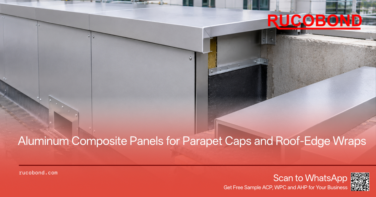
A mid-rise or high-rise wall rarely stops at the last window head. The structure continues above the roof as a parapet, and the same coated metal used on the street elevation is often asked to turn the corner and finish that free edge. From the sidewalk the parapet may read as a simple upward continuation of the wall. From the roof, and from any taller neighbor looking down, it is a three-sided condition: an outer face, a horizontal cap, and an inner face that meets the roof membrane.
The conflict starts when a single wall-panel note is extended “up and over” the roof without changing the piece. A wall cassette is usually a vertical tray, held on a backup wall or a rail, judged mainly on joint rhythm and flatness in elevation. A roof edge has a free top in the wind, a cap that has to shed water, and an inner upstand that shares space with waterproofing, insulation, and sometimes a walkway or a line of equipment. If the wall module is simply continued as a coping, the first problems are usually dimensional: the cap is too narrow once drips and outboard insulation are added, the inner skirt disappears behind the membrane termination, or joints on a dead-flat cap hold water and leave dirt tracks down the outer face.
Aluminum Composite Panels are often considered for these roof-edge wraps because the outer parapet can stay in the same coating family as the wall below, the modules can be folded into trays or channel-shaped caps, and a composite sandwich is lighter to handle on a roof than a comparable solid plate. The product still has to be specified as cladding at a roof edge, not as a generic wall leftover. It does not replace the parapet structure, the roof membrane, or the termination that keeps water out of the wall. Naming the duty early—outer face, cap, inner skirt, or a one-piece wrap—keeps widths, drip projections, and joint layout attached to the right pieces.
The three faces of a parapet are not interchangeable cuts from one elevation dimension. Treating them as a single “parapet area” is a common source of short caps and missing inner skirts.
The outer face is usually a continuation of the street or court elevation. It may be a run of cassettes stacked above the last typical wall panel, or a taller tray that starts at a horizontal transition joint and runs up to the underside of the coping fascia. Returns turn back to rails, clips, or a subframe, much as they do on the wall below, but the top of this face has to leave room for the cap’s outer drip and for any decorative cornice or cover at that junction.
The cap, or coping, sits on top of the parapet. It has to cover the structural upstand plus whatever insulation, cavity, and cladding thickness sit outboard or inboard, and then project far enough to form a drip beyond each finished face. That piece may be a separate formed cover, or the top leg of a one-piece channel that also forms the upper part of the outer and inner faces. It is the surface seen from above, and it is the surface that collects rain, dust, and, on some roofs, occasional foot traffic during maintenance.
The inner face looks back across the roof. Its usable height is not the same as the outer face. The roof membrane typically turns up this side and is terminated with a clamp, a cover strip, or a reglet, so the lower part of the inner upstand may be waterproofing, not a full-height ACP skirt. Equipment, ballast, or a roof walkway can also hide much of this face except from a taller adjacent wing.
A one-piece folded wrap reduces horizontal joints and can look continuous at the top, but the unit is heavier to lift onto the parapet, and damage to one face means replacing the whole channel. Separate outer trays, a distinct cap, and a short inner skirt are easier to handle and to replace later, at the cost of more joints that have to be detailed so water leaves the cap. Drawings should state which arrangement is intended. A parapet height on the section is not enough to infer the cut list.
An Aluminum Composite Panel is a coated aluminum-skin sandwich with a core, supplied as sheet that a fabricator can cut, route, and fold into a cassette or channel. At a roof edge, that sandwich is being asked to provide a lightweight, repeatable skin on one or more of the three faces, to take a return or a drip, and to hold a specified color with the wall below. Those are real duties, and they are limited duties.
The panel can close the visible faces of the parapet. It can be folded into trays for the outer elevation, into a channel-shaped cap, or into a short inner skirt above the membrane termination. It cannot act as the roof membrane, the through-wall flashing, or the clamp that terminates the upstand. It is not the structural concrete or steel parapet, and it is not a guard or handrail, even when the finished height looks like a protective edge. Those roles belong to the roof and parapet assembly as drawn and as required by the project documents and local code. A coated ACP cap does not, by itself, make the roof edge weathertight or safe as a fall barrier.
Geometry sets further limits. A very tight drip or a long unbroken brake-formed profile may be clearer in solid metal, which can also resist denting from tool bags and incidental contact more readily than a thin composite face. That is a difference in the surface, not a reason to treat either cap as a walkway. A composite sheet is routed before it is folded; the groove removes core and leaves a remaining skin at the bend, which is a proven way for a fabricator to form cassettes, but it is not the same as a solid plate hemmed into a narrow drip. Very large, quiet wall fields sometimes point to honeycomb panels; a narrow coping is rarely that kind of field. Rucobond supplies the panel product for these roof-edge applications. Routing, folding into trays or caps, assembly, and installation remain with the fabricator and installer. Specifying ACP for the visible skin, and leaving membrane, termination, structure, and guarding in the roof documents, keeps the material in a role it can actually hold.
The same parapet can be closed in more than one metal, and the better choice is often different for the cap than for the outer face.
ACP suits a large outer parapet face that should continue the wall below in the same coating family, in cassette modules that a crew can handle on a roof, and in inner skirts that only need to cover the band above the membrane termination. The sandwich is lighter than a solid plate of similar format, which matters when pieces are lifted over a finished membrane. It is less convincing as a drip with a very small projection and a tight hem, or as a long, almost-flat cover that will see tool bags and incidental contact, because a thin composite face dents more readily than a solid plate of similar width.
Solid aluminum veneer is often the clearer choice for the cap itself: a brake-formed cover with integral drips, a one-piece corner, or a profile that has to stay thin at the edge. A solid sheet has no core at the fold and can take a tighter hem. The tradeoff is weight, and a wide, thin solid cap can still read as oil-canned when viewed from a taller building. Color and gloss still have to be coordinated with the ACP wall below; they will not match automatically just because both metals are coated aluminum.
A mixed edge—ACP outer and inner faces with a solid aluminum cap—is a common way to use each product where it is stronger. The joint between the cap fascia and the cassette below then becomes a design line: it has to shed water, allow movement, and keep coating direction consistent around the corner. Long, simple drip legs or closure flashings are sometimes formed from prepainted aluminum coils rather than from composite sheet, especially where a continuous brake-formed profile is more practical than a routed cassette. Mixing metals is a construction decision, not a default upgrade. If people will stand or walk on the parapet during roof work, that is a structural duty for the complete edge—substrate, supports, and fixings—not a finish choice. Neither a composite cover nor a solid aluminum cap should be assumed to be a walkway simply because the metal is thicker or more dent-resistant.
A parapet height written on a section is not the size of the ACP. The usable face shrinks as soon as the cap, the drips, the membrane termination, and any decorative band are given real dimensions.
Take a worked roof-edge layout, used here as an example, not as a standard. The structural parapet is 200 mm thick and stands 1200 mm above the finished roof membrane on the inner side. Outboard of the concrete, 50 mm of insulation and a 25 mm cavity push the finished outer ACP face 75 mm in front of the wall. On the roof side, a short inner skirt stands 20 mm off the membrane face. The cap has to span that finished face-to-face width of 295 mm and then project a 25 mm drip past each face, so the overall cap is about 345 mm wide, not the 200 mm wall thickness that first appears on the structural plan.
Heights shrink in the same way. If the last typical wall joint sits 100 mm below the membrane line because of the roof assembly, the outer parapet from that joint to the top of the structure is 1300 mm. An 80 mm coping fascia hanging over the outer face, and a 50 mm transition cover or cornice at the wall-to-parapet joint, leave a usable outer ACP cassette about 1170 mm high—not the 1200 mm “parapet” in the sketch, and not the 1300 mm raw outer dimension. On the inner side, a 200 mm membrane upstand with its termination cover, plus the same 80 mm inner fascia, leaves a usable ACP skirt around 920 mm. Anyone who took 1200 mm as the inner metal height would overstate the skirt and then find the lower band already occupied by waterproofing.
Openings take more out of the field. In this layout, a primary scupper belongs at the roof drainage plane, so water already on the membrane can leave through the parapet. A worked opening 400 mm wide and 250 mm high, with a 30 mm flange, set in the lower band of the inner and outer faces and 1500 mm from an inside corner, cuts those faces and produces special trays on either side; it does not, by itself, interrupt the cap above. An emergency overflow, where the roof design includes one, is set above the primary outlet so it runs only if that path is blocked. Its height is a roof-drainage decision, not a cladding dimension, and on a 1200 mm parapet it still sits in the lower part of the wall, not immediately under the coping. Decorative cornice bands, overflow grilles, and post cut-outs likewise have to be located from the section: they are not ornaments added after the sheet is cut. A bay elevation and a roof-edge section, not a single parapet height, should drive the usable ACP dimensions.
Once the cap has a real width, the next problem is how it runs, how it turns, and where water goes. A wall joint can be a regular vertical seam. A coping joint sits in the wet plane on top of the building.
A dead-flat cap, or a cap that dished inward at mid-span, holds water at the joints and leaves dirt rings that are obvious from any higher roof or opposite tower. Many edges are therefore given a slight fall toward the roof, so overflow stays on the membrane side rather than washing down the street face. A fall toward the outer drip will keep the roof side cleaner, but it also sends stained water across the outer elevation. Neither direction is automatic; it is a choice that should be visible on the cap section, because it changes end-dam and joint direction as well as staining.
Joints themselves can be lapped, standing, or fitted with a separate cover. The point is not the joint name; it is whether the joint sheds, whether it can move with temperature, and whether it is repeated on a long run at a spacing the fabricator can actually hold flat. A long, thin cap between widely spaced joints is the piece most likely to read as wavy from above.
Corners are a different cut from a wall-panel corner. A 345 mm-wide cap turning 90 degrees produces a miter whose two legs are much wider than a typical cassette return. A shop-formed one-piece corner cap avoids a field miter at the point most exposed to wind and water, but it is a special, and it has to be scheduled with the straight runs so color and fold quality match. A field-cut miter is simpler to ship and easier to adjust, but it is also the joint most likely to open or hold dirt if the two legs are not supported and sealed as a cap, not as two wall trays butted on a diagonal.
End conditions at expansion joints, at a step in parapet height, or at a party wall need the same attention: the cap cannot simply stop as a raw sandwich edge. Drips should pass the finished faces far enough to throw water, and cut edges at joints should be closed or flashed so core is not left as a permanent drip line.
The metal joints in the cap should not be treated as the only waterproofing at the roof edge. Water can enter at a joint, at a miter, or under a drip, and the wall still has to keep that water out of the assembly. A continuous layer under the coping—an under-cap membrane or a through-wall flashing—tied into the roof upstand and given a clear path to drain, is what handles water that gets past the metal cover. The cap and its drips shed most of the weather and protect that layer; they do not replace it. How the underlayment is lapped, where it discharges, back to the roof or into the outer-wall drainage, and how cap fixings pass through or avoid it belong on the same roof-edge section as the joint layout of the metal itself.
A wall cassette is usually held along its returns, on a rail or on a backup, with the face kept clear of fasteners. A cap is a lid on a free edge. If it is detailed as if it were just another tray laid on its back, the fixings and the waterproofing start to fight each other.
Fasteners through the top face are a direct puncture in the plane that should shed water. They can be made to work with washers, sealant, and a cover, but each puncture is a maintenance point on a surface that also collects dirt. Concealed clips or secret-fixed returns at the drips keep the top cleaner, provided the clip layout can resist uplift at a free edge and the drip projection still leaves room for the clip. The wall cassettes below should not be asked to restrain a loose coping; the cap needs its own attachment back to the parapet structure or to a subframe that is part of the roof-edge assembly.
A wide, thin cap will show waviness from above more readily than a vertical tray of the same width. A rear stiffener or a formed break in the cap profile is a way to keep that field quieter. It is not a published span table. The need depends on cap width, metal build, how far the drips project, the fixing spacing, and how unforgiving the downward view is from a neighboring floor. The shop should confirm how any stiffener is attached so the outer skin, or a composite core, is not asked to hold a load it was not built for.
Wind at a free drip is resisted by the cap, the clips or fasteners, and the parapet substrate or subframe they anchor to, acting as one assembly. The wind performance of that edge is not a property of the sheet alone. A panel thickness or a cassette build does not, by itself, establish that the cap will stay in place; clip spacing, anchorage into a sound base, and how those fixings pass through or avoid the under-coping waterproofing have to be designed together. Otherwise a tight-looking cover can still lift, or the fixings can puncture the layer that is supposed to remain watertight.
Uplift and handling are also different from a wall bay. A cap can be lifted by wind at the drip, and it is often installed after the membrane, when crews are working on a finished roof. Piece length is therefore a trade between fewer joints and what can be lifted, aligned, and fastened safely at the edge. Those lengths belong on the shop drawings; they should not be inferred from the wall-module grid below.
Color at a roof edge is judged in two directions, and they do not forgive the same things. The outer fascia is read with the wall below, often at street distance. The cap is read from above: from a higher plant room, from an opposite wing, or from a neighboring tower. A finish that looks even in elevation can still look restless on the horizontal plane.
Metallic and mica coatings are the clearest example. Flake orientation on a horizontal cap will not automatically match the vertical face below, even when both pieces come from the same coating family and color code. If the cap, the outer fascia, and the wall are meant to read as one metal, coating direction and viewing samples should include a horizontal piece, not only a vertical wall sample. High gloss on the cap will also show residual waviness and footprints more readily than a lower sheen, and it will show them to anyone looking down.
Soiling is part of the same viewing condition. Low spots and joints collect dust and ponded water; birds use a quiet cap; pollen and bitumen tracking from roof work leave fans of dirt. When water finally leaves over the outer drip, it can wash that dirt down the street face in repeating streaks under each joint or low point. A slight fall to the roof side, a cleaner drip edge, and a joint layout that does not sit in a dip will not make the cap self-cleaning, but they do change how the wall below weathers. Tool bags, ladder pads, or incidental contact can also leave scuff marks on a high-gloss or dark solid color, which is a reason a lower-sheen coating is sometimes chosen for the top only, while the wall faces stay in the original ACP finish. That is an appearance choice; it does not make the cap a walkway.
Night viewing is less about interior light than about roof equipment and cornice lighting. A glossy cap under a nearby floodlight will read every wave and joint; a matte cap will recede. Finish samples for a roof edge should be looked at horizontally, in daylight and under a hard side light, not only as small vertical chips against a wall board.
A parapet is also where roof drainage, fall protection, and sometimes a mechanical screen meet the same edge. The ACP skin can be cut and folded around those items. It should not be asked to be those items.
A scupper or overflow opening has to pass water through the parapet at the drainage plane the roof design intends—typically at the membrane for a primary outlet, and somewhat above it for an emergency overflow. The waterproofing of that opening is a sleeve, a liner, or a formed metal scupper with a flange that ties into the roof membrane and the outer weather plane. The ACP faces can receive a neat, flanged opening, with special trays on either side; the cap above can usually continue across that bay. The panel is not the scupper. If the opening is treated as a hole cut in a finished cassette after coating, the exposed core and the missing flange show up immediately, and the drainage path is no longer the roof assembly’s.
Guards and handrails are a structural duty. Post bases want a plate or a plinth that is anchored to the parapet structure, with the cap or outer skin cut and flashed around the post. A hollow ACP cassette is not a foundation for a guard post, and a coping is not a handrail, even when the finished parapet height looks as if it could serve as one. Local code and the project’s fall-protection design govern that height and the guard; the coated cap does not.
Rooftop equipment screens often stand just inside the parapet, or rise above it. They are a separate assembly, with their own posts, access panels, and, where airflow is required, perforated or louvered faces. The parapet cap should be detailed to end cleanly at those posts and access routes, not stretched into a continuous screen. Screening, airflow, and equipment access are their own problem; the roof-edge wrap should not be rewritten as a mechanical enclosure. Keeping scuppers, guards, and screens in their own documents, and sending the ACP fabricator the openings and interfaces, is what lets the skin fit the edge without taking on work it cannot do.
An enquiry that only lists color, thickness, and total square meters will be priced as generic sheet. A roof-edge package prices correctly when the enquiry shows which faces are being made and how they sit on the parapet.
The note should state whether the Aluminum Composite Panel is the outer face, the cap, the inner skirt, a one-piece wrap, or a mix with a solid aluminum cap or coil-formed flashings. A typical roof-edge section should show structural thickness, insulation and cavity, membrane upstand height, drip projections, cap fall, and the last wall joint below. Heights and widths on that section, not a single parapet dimension, should be the basis for quantities. Quantities should be split into typical outer trays, typical caps, inner skirts, and specials: corners, scupper bays, post cut-outs, steps in parapet height, and end conditions at expansion joints.
Panel build should follow the project documents: overall thickness, aluminum skin gauge, core type, and any fire-performance requirement as those documents state it. Coating family, color, gloss, and metallic direction should be referenced for the vertical faces and, separately where it matters, for the horizontal cap. The usual request is panel product as flat sheet; the fabricator then cuts, routes, or folds it into wall cassettes, caps, or a combination.
If the parapet must support foot traffic, or if a guard, scupper, door, or screen interface occurs on the same edge, that duty should be on the enquiry with the relevant openings, so the complete assembly—not only the visible metal—can be considered. Contractors, fabricators, importers, and distributors can send those sections and notes to Rucobond when requesting Aluminum Composite Panels for parapet caps and roof-edge wraps. A short typical-edge package is enough to start a specific quotation; a parapet height on an elevation is not.
Q: Can an Aluminum Composite Panel replace the roof membrane or the parapet waterproofing termination? A: No. ACP is the visible skin on the outer face, the cap, the inner skirt, or a one-piece wrap. The membrane, the upstand, and the clamp or cover that terminates it are part of the roof assembly and should stay in the roof documents. The panel can be detailed around that termination; it is not a substitute for it.
Q: Why is the usable ACP face smaller than the parapet height on the section? A: The parapet height includes the coping fascia, drips, any transition cover or cornice, and, on the inner side, the membrane upstand and its termination. A worked example with a 1200 mm inner height can leave an outer cassette around 1170 mm and an inner skirt around 920 mm once those pieces are given dimensions. A primary scupper at the roof drainage plane shrinks the lower face field in that bay, but it does not, by itself, cut the cap. Post cut-outs and other openings shrink the field where they actually occur. A roof-edge section, not the parapet height alone, should drive the cut size.
Q: Should the cap be ACP, solid aluminum, or a mix? A: ACP is often a good fit for the outer parapet face and a short inner skirt that continue the wall coating. A solid aluminum cap is often clearer for tight drips and brake-formed covers, and it may resist denting from incidental contact more readily. Neither metal, used only as a cover, should be assumed to be a walkable cap; if people must walk the parapet, that duty belongs to the complete supported assembly. A mixed edge uses each metal where it is stronger, but color, gloss, and the joint under the fascia have to be coordinated.
Q: Is an ACP coping a guard or a walkable maintenance path? A: No. A coated cap is cladding on top of the parapet. It is not a handrail or a fall barrier, and a hollow cassette is not a foundation for a guard post. Solid aluminum may dent less readily than a thin composite face, but that is a surface difference. Neither material automatically gives the cap a walkable capacity; if crews must walk the parapet, the substrate, supports, and fixings have to be designed for that load.
Q: What should be sent with a parapet or roof-edge ACP enquiry? A: Which faces are ACP; whether the cap is intended in ACP, solid aluminum, or coil-formed sheet; a typical roof-edge section with thickness, cavity, membrane upstand, under-coping waterproofing, drips, and cap fall; quantities of typical pieces versus corners, scupper bays, and post cut-outs; thickness, skin gauge, and core as specified; coating and finish direction for vertical and horizontal faces; and that the material is required as panel sheet for the fabricator to form. Fire-performance requirements should be copied from the project documents when they apply.
Name: Gina Chen
Mobile:+86-189-2412-4951
Tel:+86-189-2412-4951
Whatsapp:8618924124951
Email:gina@rucobond.com
Add:Room 708, No. 8 Jingang Avenue, Nansha Street, Nansha District, Guangzhou


