
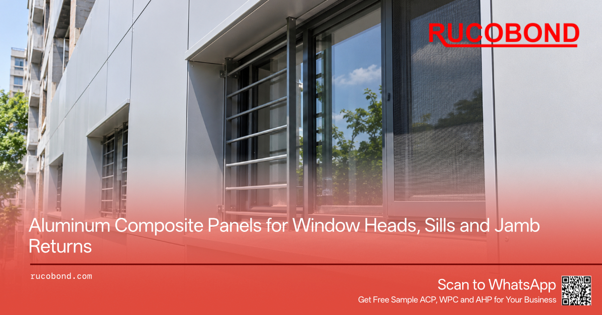
In many mid-rise streets across Southeast Asia and Pakistan, the apartment, office, or hotel is still a concrete frame with masonry infill, or a concrete wall, and the windows are holes in that solid wall. The opening is formed in the structure, a window unit is set into it, and the street elevation is finished around the hole. That punched window, not a full glass grid, is often the main way light and air enter the room. Security grilles, insect screens, and a split air-conditioning unit on the same wall are ordinary parts of the same opening, not special cases.
The weather at that opening is not the same in every city, and the wall is not a single regional type. In Singapore or Bangkok, high humidity, heavy rain, and the need to drain and shade the opening often set the reveal depth and the sill slope. In Karachi, coastal salt and dust sit on the metal and make cleaning of the sill, and of shaded returns, a practical concern. In Lahore, hot summers, wind-blown dust, and rain in the monsoon months put the same opening under heat, soiling, and periodic wetting. These are site examples; they do not mean that every building in Southeast Asia or Pakistan is detailed the same way.
That is a different condition from a curtain-wall spandrel or a window-wall infill. In a glazed grid, the opaque panel sits in a bay defined by mullions and transoms, or it covers a slab edge between stacked window units. The framing of the glass wall is already there; the panel fills a rectangle in that grid. A punched opening on a concrete or masonry mid-rise has no such grid. The window sits in a rough opening, the wall cladding has to stop, turn, and finish against the frame, and the waterproofing of the opening—head flashing, sill pan, end dams, and the air and water barrier on the wall—belongs to the window and wall assembly, not to the decorative wrap.
The conflict starts when a wall-panel module drawn for a dry, shallow elevation is simply stopped at the opening and asked to “trim” the window. A wall cassette is judged mainly in elevation: joint rhythm, flatness, and color with the field. A window surround is judged in section and in weather at the same time. The head is a short soffit as well as a face, and on a sun-struck wall the window is often set deep in the opening, so that soffit is longer than a street elevation suggests. The jamb is a return as well as a pier, and it may have to clear a grille frame or a screen track. The sill is a sloped tray that will take monsoon rain, dust, and runoff from glass cleaning, and it will be seen from the room and from the street. If those pieces are cut from the elevation width and height alone, the first shortages appear at the returns: the soffit is too shallow once a drip and a deep reveal are folded in, the sill becomes a dirt shelf once the slope is lost, or the jamb return covers the window’s weeps, the screen, or the grille.
Aluminum Composite Panels are often considered for these surrounds because the field wall, the head, the jambs, and, on some projects, the sill can stay in the same coating family, and a composite sheet can be routed and folded into the trays and channels those four positions need. The product still has to be specified as cladding around an opening in this kind of building, not as a generic wall leftover and not as a substitute for the window, the lintel, the flashing, or the grille. Naming the duty early—field, head, jamb, sill, or a mixed surround—keeps reveal depth, drip projections, and the extra parts at the opening attached to the right pieces.
The four positions around a punched window are not interchangeable cuts from one opening dimension. Treating them as a single “window trim area” is a common source of short sills and jamb returns that collide with the frame, the screen, or a sun-shade reveal.
The field wall is the cladding that runs between openings and above or below them. On a mid-rise concrete or masonry block it may be a run of cassettes on furring or rails, with joints that continue the elevation module. At the opening, this field does not simply die on a raw cut edge. It has to meet a head, a jamb, or a sill with a planned joint, a folded corner, or a continuous wrap, so the edge of the opening reads as a finished return rather than a saw cut through the street wall.
The head sits above the window. Its outer face is the wall above the opening, and its underside is a soffit that returns toward the window frame. In a shallow street wall that soffit may be only a short hem. Where the window is set deep for shade, which is a frequent choice on sun-struck elevations, the soffit becomes a real underside, visible from the sidewalk and long enough to accumulate airborne grime or insect residue over time. That soiling is not the same as dust settling on the sloped sill: the soffit faces down, so it does not collect a settled film the way a horizontal tray does. The bottom edge of the head face usually needs a drip so monsoon water running down the wall does not follow the soffit back toward the window. The inner edge of the soffit has to stop in a way that leaves the head flashing and any window weeps or receptor outlets able to drain.
The jambs sit at each side of the opening. Their outer faces are the piers between windows, or the wall at an end opening. Their returns turn into the opening and finish against the frame, a sealant joint, or a separate frame cover. A narrow pier between two apartment windows is doing two returns at once. Those returns turn into the opening; they do not, by themselves, narrow the finished face seen from the street. The finished face is the width between the fold lines at the opening edges, unless the project moves those folds inboard or takes joints and trim from the flat. If a security grille or a sliding screen is later fixed in the reveal, the return also has to leave that frame a clear landing on the structure, not on the cladding.
The sill is the piece that leaves the opening. It is a sloped tray, not a flat shelf copied from the wall module, and at the opening it is the surface that does the most work. In section it typically has an outer drip that projects beyond the wall face, a sloped surface that sheds heavy rain, and an inner upstand or hem at the window. At each end it may carry a dam, or it may run through under the jamb returns. It is seen from the room and from the street, and it holds dust, pollen, salt film on a coastal site, and runoff from glass cleaning. The decorative sill sits over, not in place of, the waterproof sill pan and the window’s own drainage. It is also not a shelf for planters, laundry, or an outdoor condensing unit.
An Aluminum Composite Panel is a coated aluminum-skin sandwich with a core, supplied as sheet that a fabricator can cut, route, and fold into a cassette, a return, or a sill tray. At a punched window on this kind of mid-rise, that sandwich is being asked to provide a lightweight, repeatable skin on the field and on one or more of the three opening faces, to take a drip or a return, and to hold a specified color with the wall in strong sun. Those are real duties, and they are limited duties.
The panel does not carry the wall above the opening. A lintel, a bonded beam, or a framed header does that work, and the head wrap has to leave the structure and its movement joints alone. The panel is not the window. It does not provide the air, water, or structural performance of the glazing unit, and it should not be used to correct a frame that is out of the opening. The panel is not the waterproofing of the opening. Head flashing, a sill pan with end dams, membrane or coating at the rough opening, and the wall’s air and water barrier are what keep monsoon water out of the backup; the decorative metal is a rain screen or a finished cover over that work. A coastal site, a dusty inland street, or a shaded humid wall does not change that division of work, and it does not turn the composite sheet into a weathering membrane.
Geometry sets further limits. A very tight drip, a thin brake-formed sill, or a long unbroken sill profile may be clearer in solid metal, which can also resist denting from ladders, window-washing tools, and incidental contact more readily than a thin composite face. That is a difference in the surface, not a reason to treat either sill as a step, a seat, or a service platform for an air-conditioning unit. A composite sheet is routed before it is folded; the groove removes core and leaves a remaining skin at the bend, which is a proven way for a fabricator to form trays, but it is not the same as a solid plate hemmed into a narrow drip or an upstand. Very large, quiet wall fields sometimes point to honeycomb panels; a narrow sill or a short jamb return is rarely that kind of field.
Rucobond supplies the panel product for these opening wraps. Routing, folding into trays or surrounds, assembly, and installation remain with the fabricator and installer. Specifying ACP for the visible skin, and leaving the window, lintel, flashing, grille, and barrier in the opening documents, keeps the material in a role it can actually hold.
The same opening can take a single metal throughout, or it can mix metals by position. The choice is not a matter of preference alone; it follows from what each face is being asked to do on this wall and in this weather.
ACP is usually the stronger choice where the surround has to continue a large wall field in the same coating, where the head face and the piers are wide enough for a cassette module, and where the returns can be routed and folded without asking the panel for a very tight, long hem. The field, the head face, and the jamb faces are the positions where that match to the wall matters most, because they are read together in elevation on a long mid-rise street wall.
Solid aluminum panels are often clearer at the sill, and sometimes at a very shallow head soffit or a thin frame cover. A brake-formed solid plate can take a tight drip and a small upstand without a routed groove, and the thicker surface metal is less ready to show a dent when a tool, a ladder, or daily window cleaning lands on the sill. On a coastal sill in a city such as Karachi, salt film collects; on an inland street in Lahore, dust sits on the tray; in a humid, high-rainfall city such as Singapore or Bangkok, the same tray takes repeated wetting and dirty runoff. A tougher, tighter sill profile is often the practical answer to that wear. Dent resistance is still a surface property. It does not make the sill a walkable ledge, and it does not make the metal a waterproof pan. A decorative solid-aluminum sill still sits over the opening’s own drainage parts.
A mixed surround—ACP on the field, head, and jambs, and a solid aluminum or coil-formed sill—is a frequent way to handle that split. It keeps the wall color continuous where the eye reads the elevation, and it puts a tighter profile where water, dust, and contact collect. The tradeoff is at the joints where the two metals meet, usually at the underside of the jamb return or at the ends of the sill. Color, gloss, and metallic direction have to be coordinated there, or a “same color” sill will still read as a different piece in hard sunlight. Coated aluminum coils are sometimes the source for complementary flashings or for a brake-formed sill when the project wants a thinner, longer profile than a composite tray; those coils are not a substitute for the wall panel, and they are not, by themselves, the sill pan.
Honeycomb panels belong in a different conversation. They are a fit for large, quiet faces that need stiffness across a wide module. They are not a natural choice for a narrow sloped sill or a short jamb return, and forcing them into those pieces adds weight and edge-closing work without solving the opening.
The opening size on the elevation is not the size of the metal the fabricator has to cut. Reveal depth, drips, furring, the position of the window in the wall, and the clearance reserved for a screen or grille all change the blank, and some of them change the visible face. A worked example makes those dimensions concrete. The figures below describe one illustrative opening on a mid-rise masonry-infill wall; they are not a standard, a recommended set, or a performance claim, and wall build-ups vary widely from one city and building type to another.
Take a 200 mm masonry infill in a concrete frame, with a punched opening 1500 mm wide and 1800 mm high. Outboard of the masonry, plaster and a furring cavity add 40 mm to the back of the panel. The window is set 150 mm inboard of the masonry’s outer face, a modest sun-shade reveal rather than a flush street window. The return depth—the distance from the cladding plane to the frame—is then about 190 mm (40 mm of furring plus the 150 mm setback). The window is smaller than the opening by a 25 mm perimeter joint, so the unit is 1450 mm wide and 1750 mm high. None of those dimensions is a rule for other walls. A flush window on a shallow cavity can shrink the return depth to a tight fold of around 40 mm. A deeper shade reveal, or a thicker insulated backup, lengthens every soffit, jamb, and sill.
Three measurements need to be kept apart on every piece: the finished face, which is the visible flat on the street or on the underside; the return depth, which is how far the metal turns into the opening; and the developed blank, which is the flat sheet the fabricator actually cuts, including drips, returns, and hems.
The head face on this wall might run 600 mm, measured on the cladding plane, from the head of the structural opening up to a floor-line joint or the slab edge above. If an 80 mm transition cover or decorative band occupies the top of that height, the finished face height of the ACP head is about 520 mm (600 minus 80). The 25 mm drip at the bottom is a downturned fold at the leading edge of the soffit. It hangs below the finished face and is added to the developed blank; it is not deducted from the 600 mm height or from the 520 mm face. The soffit still has to cross the 190 mm return depth to the frame. The drip does not, by itself, shorten that horizontal depth; a 20 mm cover or hem at the window does. The visible flat soffit in this layout is therefore on the order of 170 mm, depending on how the hem is formed. A one-piece head blank, illustrated here only as a sum of those parts, is the 520 mm finished face, plus the 25 mm drip, plus the soffit that crosses the 190 mm return, plus the hem at the frame. If the head wrap is cut from the 600 mm elevation height alone, the soffit and the drip are the pieces that disappear—and on a deep sun-shade reveal, that missing soffit is a large, visible underside.
A pier between two such apartment openings may be 600 mm of masonry. If the fold lines sit at the opening edges, and the jamb returns turn into the reveal, the finished face width of the pier at the cladding plane remains about 600 mm. Those returns do not, by themselves, reduce the street face. The finished face would be narrower only if the project moves the fold lines inboard—for example, to form a vertical drip or a setback on the face—or if joint width and fabrication trim are taken from the flat. Each jamb return still has to cross the same 190 mm return depth to the frame, and a hem, frame cover, or grille landing shortens the visible inside return, not automatically the pier face. The developed blank for a pier piece is the finished face width plus the return or returns, plus any drips and hems. On a narrow pier, two deep returns can make a demanding blank even when the finished face stays close to the 600 mm masonry width.
The sill is where the developed blank is most often underestimated, especially when the reveal is deep. In this example the tray has a 25 mm outer drip beyond the wall face, a sloped surface that crosses the 190 mm return depth to the window, and a 25 mm inner upstand at the frame. The sloped face is slightly longer than 190 mm because it is pitched; the actual developed length depends on the pitch chosen for the project, which is a drainage decision, not a fixed millimetre in this article. A tray that is drawn flat “to look like the wall” will hold rain and dust instead of shedding them. If the sill is fitted between jamb returns rather than run through under them, each end also needs a dam, illustrated here as a 25 mm fold. Those dams do not always shorten the sloping face, but they do have to be formed from the same blank, and they have to stop against the jamb without tearing the coating at the corner. A sill drawn as “1500 mm wide by 190 mm deep” on the elevation is therefore not a rectangle of that size in the workshop: 1500 mm may be the finished length between jambs, 190 mm is the return depth, and the developed blank is longer once the drip, the slope, the upstand, and any dams are unfolded.
Sending the fabricator a section that shows the actual wall, the window setback, drips, the reserved joint at the frame, and any grille or screen clearance is what turns the elevation opening into a set of blanks that actually fit. A width and height taken from the architectural elevation will not.
Water at a punched window does not leave only along the joints in the decorative metal. Seasonal monsoon rain, and wind-driven rain on an exposed elevation, put more water at the opening than a light shower on a sheltered wall. The visible sill is one surface in a larger drainage path, and the joints in that sill are not the waterproofing of the opening.
Rain that hits the glass runs to the window’s own sills and weeps, or it is shed onto the decorative tray. Water that hits the tray should run down the slope and drip clear of the wall face, which is why the outer edge is turned down and projected. Joints in a long sill—laps, standing seams, or separate covers—should shed in the same direction and should be spaced so the tray can move with high daytime temperatures without buckling. A dead-flat, tightly butted joint on a long run is the joint most likely to hold water and leave dirt tracks down the wall below, and it is also the joint that holds dust after the rain stops.
What the decorative joints cannot do is replace the sill pan, the end dams in the waterproofing, or the head flashing. Those parts sit under or behind the metal. The pan collects water that gets past the window or past the outer tray and directs it back out, over the wall’s drainage plane, rather than into the masonry or the concrete backup. End dams at the jambs stop that water from running sideways into the pier. Head flashing above the window collects water from the wall above and sheds it over or around the unit. The ACP head, jambs, and sill have to be coordinated with those parts so that a screw, a clip, or a return does not puncture the pan, pinch a dam, or turn the head flashing’s outlet back into the opening. A wet season does not change that requirement; it only makes a blocked path show up sooner.
Two sill patterns appear often, and they fail in different ways if the drainage path is ignored. A sill that runs through under the jamb returns can carry water the full width of the opening and past the jamb, which is a clean idea only if the pan and dams are also continuous and the jamb returns are held off the drainage surface. A sill fitted between the jambs, with metal end dams formed in the tray, is easier to handle as a unit, but it dumps its responsibility onto the joint at each jamb; that joint has to sit above the waterproof dams, not in place of them. In either pattern, sealant in the decorative joint is a finish and a rain screen aid, not a substitute for the pan, and it should not be asked to make up for a tray that was installed flat.
Corners at the jamb-sill and jamb-head meetings are miters or folded intersections, not places to hide a change in plane with a blob of sealant. A miter that opens under sun load will show a bright cut edge and a dirt line; a fold that is planned as a one-piece corner avoids that cut but has to be allowed for in the blank. Neither detail makes the metal watertight on its own. The surround is finished when the decorative joints shed, the flashing path is still open, and the two are no longer being asked to do each other’s work.
A wall cassette is usually hung on rails or clips across a flat backup, with fasteners in returns that stay in the cavity. A window surround uses some of the same hardware, but the head soffit, the jamb return, and the sloped sill do not behave like another wall bay, and they should not be fixed as if they did.
The head soffit is a short horizontal face in the wind. Suction at the wall’s outer plane, including during monsoon squalls, tries to pull that soffit down and out, and the piece is only as stable as the clips or channels that tie it back to the lintel zone or to the wall framing. The resistance is not a property of the composite sheet alone. It is the capacity of the complete head assembly: the formed soffit, the clips or rails, the fasteners, and the substrate they engage. A thicker skin or a solid-aluminum soffit may feel stiffer in the hand; it still does not create a wind rating by itself.
The jamb return is a narrow, deep piece, and on a sun-shade reveal it is deeper than a flush street window. Fasteners that are easy to place in a wide wall cassette are harder to hide here, and a screw that is driven too close to the window can miss the backup and land in the perimeter joint or in a screen track. The return should be held on a subframe or on clips that leave the sealant joint, the frame covers, and any grille fixings free to work. Where two returns share a narrow apartment pier, the subframe has to leave room for both pieces and for the movement joint in the field, rather than sharing a single overloaded clip line.
The sill is the piece most often fixed in a way that later shows up as a leak. A screw through the sloped face into the rough opening is a hole in the decorative metal and, if it goes deep enough, a hole in the sill pan. Isolated clips, a hat channel, or supports that stop above the pan keep the tray in line without puncturing the waterproofing. The inner upstand should not be used as a clamp on the window frame, and the outer drip should not be hard-fastened back to the wall face in a way that pulls the slope flat. A sill that has been pulled flat will pond in the wet season and cake with dust in the dry season.
Fixings also have to allow the surround to move. Aluminum and a masonry or concrete backup do not change length at the same rate, and a long head fascia or a long sill on a sun-struck elevation will telegraph oil-canning or open a miter if it is fixed hard at every point. Joints planned for movement, and clips that let the tray breathe between them, are part of the assembly, not an optional extra. Wind, movement, and weather tightness are all properties of that assembly. They are not sheet marks to be read off a composite panel by itself, and they are not altered by naming a city or a climate on the drawing.
A punched-window surround is seen from more angles than the wall it sits in, and it soils in a different pattern. Color that is acceptable on a vertical field can still fail around the opening if those conditions are ignored.
The field and the jamb faces are read in elevation, in hard sunlight, in the same light as the wall. The head soffit is seen from below, often in shade, and it picks up a darker or flatter reading than the face above it, especially in a metallic or pearlescent coating. On a deep reveal that shaded soffit is a large surface, and over time it can accumulate airborne grime or insect residue; it does not take a settled dust film the way the sill does. The sill is seen from the room, from a balcony, and, on a low opening, from the sidewalk looking slightly down. It is a near-horizontal surface, so it holds dust on an inland ledge, salt film on a coastal site such as Karachi, leaf stain, and the runoff from glass cleaning. A high-gloss light color will show that film earlier than a mid-gloss or a slightly darker tone in the same family. The point is not to invent a dirt-proof or salt-proof finish, or a service life in the sun; it is to choose the sill finish knowing it will be viewed up close and will not stay as clean as the wall.
Metallic and brushed coatings have a direction. A jamb return turns that direction ninety degrees from the face, and a head soffit turns it again. If the grain or the flake orientation is not planned for the returns, the opening will read as a darker frame even when the color code is the same, and strong sun makes that shift more obvious. The sill, if it is in the same metallic, will also read differently because it is viewed at a steeper angle. Some projects accept that change and keep one product throughout. Others put a solid, non-metallic color on the sill and soffit, or they cut the returns so the grain stays consistent around the opening. Either choice should be made on a sample that includes a return, and that sample should be looked at in sun and in shade, not only as a flat chip held against the wall indoors.
Joint lines around the opening are read at arm’s length by occupants and at street distance by everyone else. A wide, uneven reveal at the frame, or a sill joint that does not line up with a jamb miter, becomes the thing the eye finds first. Aligning those joints with the wall module where it is reasonable, and keeping the reserved sealant joint at the frame consistent around the perimeter, does more for the appearance of the surround than a new color would.
The wrap around a punched window sits next to several parts it can conceal and none it can replace. On many mid-rise walls in these cities, those parts often include a security grille, an insect screen, and a split air-conditioning unit as well as the lintel and the window’s own drainage. Keeping them in their own documents is what prevents the ACP from being asked to close a gap it cannot close.
The lintel, or the header in a framed wall, carries the wall above the opening. The head wrap may cover the lintel’s outer face and turn under it, but the metal is not a substitute for the lintel’s bearing, its insulation, or any movement joint the structure needs. Fastening the soffit should not stitch the lintel to a cladding rail in a way that fights that joint.
Weeps and drainage outlets have to stay open. Many windows discharge at the sill; some head receptors and flashings also need a clear outlet at the top of the unit. An ACP head return that is run tight to the frame for a clean look can cover those outlets or pinch the head flashing so it no longer drains. The clearance at that inner edge is a coordination item with the window system, not a single millimetre that can be copied from one project to another. The surround should be drawn so the decorative hem stops short of the weep path, and so any frame cover is part of the window or flashing design rather than an improvised extension of the ACP.
Security grilles and insect screens are fixed to the structure or to the window, not to the cladding. The ACP return should be notched or stopped so the grille frame has a solid landing and the screen track remains usable. The panel is not a grille, it is not a burglar bar, and it should not be drilled as a convenient post base. A split outdoor unit on a wall bracket beside or below the window needs its own support, a clear service space, and a place for condensate to drain that is not the decorative sill. The sill tray is not an equipment pad, and condensate should not be asked to run across a finished ACP face as a substitute for a drain.
A decorative sill is not a guard and it is not a step. On an upper floor, the window’s sill height, a rail, or a separate guard is what addresses a fall; a formed metal tray, whether composite or solid aluminum, does not become a barrier by being stiffer or thicker. The same tray should not be treated as a walkable ledge for window washing or for standing plants. Solid aluminum may dent less readily than a thin composite face, but that is still a surface difference, not a load rating for the assembly. If a person must stand at the opening, that duty belongs to the structure, the supports, and the completed assembly designed for it.
Sunshades and blind boxes are also separate from the wrap. A shade fin or a box may need a clear fixing zone at the head or jamb; the ACP should be notched or stopped for that bracket, not asked to become the fin. Sending the fabricator the window schedule, the weep and flashing notes, and the grille, screen, shade, and air-conditioning interfaces keeps the skin around the opening, and leaves structure, drainage, security, and services in the assemblies that actually provide them.
An elevation with a window width and a color chip is not enough to quote a surround. The enquiry is more useful when it describes the opening the way the fabricator will have to form it on this building.
A typical section through the head, jamb, and sill should show the wall thickness, the furring or cavity, the position of the window in the opening, the planned return depths, drips, and the reserved joint at the frame. If a waterproof sill pan, end dams, or head flashing already exist in the window or wall drawings, those parts should be on the same section so the decorative metal can be kept off the drainage path. An opening schedule—widths, heights, counts, and any raked, arched, or unusually deep shade reveals—separates typical blanks from corners and specials. A note on whether the site is coastal or inland, and whether grilles, screens, or outdoor air-conditioning units share the opening, tells the fabricator what clearances and interfaces to expect. It is not a request for a climate rating of the sheet.
The enquiry should say which faces are ACP and whether the sill is intended in ACP, solid aluminum, or coil-formed sheet. A mixed surround should note where the two metals meet. Panel build should follow the project documents: overall thickness, aluminum skin gauge, core type, and any fire-performance requirement as those documents state it. Coating family, color, gloss, and metallic direction should be referenced for the vertical faces and, separately where it matters, for the sill and the head soffit. The usual request is panel product as flat sheet; the fabricator then cuts, routes, or folds it into field cassettes, returns, and trays.
If a shade bracket, a guard, a grille, a screen, or an air-conditioning support lands on the same opening, that interface should be on the enquiry with the relevant openings, so the complete assembly—not only the visible metal—can be considered. Contractors, fabricators, importers, and distributors can send those sections and notes to Rucobond when requesting Aluminum Composite Panels for window heads, sills, and jamb returns. A short typical-opening package is enough to start a specific quotation; a window width on an elevation is not.
Q: Can an Aluminum Composite Panel replace the waterproof sill pan or the window flashing? A: No. ACP can form the visible head, jambs, and a decorative sill tray, but it is not the opening’s waterproofing. The sill pan, end dams, head flashing, and the wall’s air and water barrier remain part of the window and wall assembly. Monsoon rain makes a blocked path show up sooner; it does not transfer that duty to the decorative metal. Joints in the visible tray should shed water; they do not take the place of the drainage path.
Q: Why is the usable ACP face smaller than the opening shown on the elevation? A: The elevation shows the hole in the wall. The fabricator has to form drips, returns, hems, and, at the sill, a slope and often end dams. Furring, a sun-shade reveal, and the window’s setback set the return depth, and a reserved sealant joint, screen track, or grille frame at the opening shortens the inner edge of the return, not automatically the finished face of the pier. The developed blank is larger than the finished face once those folds are unfolded, which is why a typical section from the project wall is more useful than the opening size alone.
Q: Should the sill be ACP, solid aluminum, or a mix with ACP heads and jambs? A: ACP is often a good fit for the field, the head, and the jambs when those faces should continue the wall coating. A solid aluminum sill is often clearer for tight drips, for contact during glass cleaning, and for a tray that will take dust, salt film, or repeated wetting, because the surface metal can resist denting more readily. Neither metal, used only as a decorative tray, should be assumed to be a walkable ledge or an equipment pad. A mixed surround uses each metal where it is stronger, but color, gloss, and the joint at the jamb have to be coordinated in strong sun.
Q: Is an ACP window sill a walkable ledge, a guard, or a stand for an air-conditioning unit? A: No. A coated sill tray is cladding at the bottom of the opening. It is not a step, a seat, a fall barrier, or a pad for an outdoor unit, and it should not be used as a foundation for a grille post. Solid aluminum may dent less readily than a thin composite face, but that is a surface difference. Neither material automatically gives the sill a walkable or guarding capacity; if people must stand at the opening, or if a guard, grille, or condensing unit is required, that duty belongs to the complete supported assembly designed for it.
Q: What should be sent with a punched-window ACP enquiry? A: Which faces are ACP; whether the sill is intended in ACP, solid aluminum, or coil-formed sheet; a typical head, jamb, and sill section with wall thickness, furring, window setback, drips, returns, under-sill waterproofing, and the reserved joint at the frame; an opening schedule, including deep reveals and specials; any grille, screen, shade, or air-conditioning interface; thickness, skin gauge, and core as specified; coating and finish direction for vertical faces, soffits, and sills; a brief note on whether the site is coastal or inland; and that the material is required as panel sheet for the fabricator to form. Fire-performance requirements should be copied from the project documents when they apply.
Name: Gina Chen
Mobile:+86-189-2412-4951
Tel:+86-189-2412-4951
Whatsapp:8618924124951
Email:gina@rucobond.com
Add:Room 708, No. 8 Jingang Avenue, Nansha Street, Nansha District, Guangzhou


